Importing is achieved by the import() command.
[Note: Requires version 2015.03-2] The File >> Open command may be used to insert this command. The file type filter of the Open File dialog may show only OpenSCAD files, but file name can be replaced with a wildcard (e.g. *.stl) to browse to additional file types.
import
Imports a file for use in the current OpenSCAD model. The file extension is used to determine which type.
- 3D formats
- STL (both ASCII and Binary)
- OFF
- AMF [Note: Requires version 2019.05]
- 3MF [Note: Requires version 2019.05]
- 2D formats
- DXF
- SVG [Note: Requires version 2019.05]
- Other
- CSG can be imported using include<> or loaded like an SCAD file, PNG can be imported using surface()
Parameters
- <file>
- A string containing the path to file.:If the give path is not absolute, it is resolved relative to the importing script. Note that when using
include<>with a script that usesimport(), this is relative to the script doing theinclude<>. - <convexity>
- An Integer. The convexity parameter specifies the maximum number of front sides (back sides) a ray intersecting the object might penetrate. This parameter is needed only for correctly displaying the object in OpenCSG preview mode and has no effect on the polyhedron rendering. Optional.
- <layer>
- For DXF import only, specify a specific layer to import. Optional.
import("example012.stl", convexity=3);
import("D:/Documents and Settings/User/My Documents/Gear.stl", convexity=3);
(Windows users must "escape" the backslashes by writing them doubled, or replace the backslashes with forward slashes.)
Read a layer of a 2D DXF file and create a 3D shape.
linear_extrude(height = 5, center = true, convexity = 10)
        import_dxf(file = "example009.dxf", layer = "plate");
Convexity
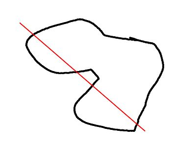
This image shows a 2D shape with a convexity of 4, as the ray indicated in red crosses the 2D shape a maximum of 4 times. The convexity of a 3D shape would be determined in a similar way. Setting it to 10 should work fine for most cases.
Notes
In the latest version of OpenSCAD, import() is now used for importing both 2D (DXF for extrusion) and 3D (STL) files.
If you want to render the imported STL file later, you have to make sure that the STL file is "clean". This means that the mesh has to be manifold and should not contain holes nor self-intersections. If the STL is not clean, it might initially import and preview fine, but then as soon as you attempt to perform computational geometry on it by rendering a combination of it with something else, you might get warnings about it not being manifold, your imported stl might disappear from the output entirely, or you might get errors like:
 CGAL error in CGAL_Build_PolySet: CGAL ERROR: assertion violation!
 Expr: check_protocoll == 0
 File: /home/don/openscad_deps/mxe/usr/i686-pc-mingw32/include/CGAL/Polyhedron_incremental_builder_3.h
 Line: 199
or
 CGAL error in CGAL_Nef_polyhedron3(): CGAL ERROR: assertion violation!
 Expr: pe_prev->is_border() || !internal::Plane_constructor<Plane>::get_plane(pe_prev->facet(),pe_prev->facet()->plane()).is_degenerate()
 File: /home/don/openscad_deps/mxe/usr/i686-pc-mingw32/include/CGAL/Nef_3/polyhedron_3_to_nef_3.h
 Line: 253
In order to clean the STL file, you have the following options:
- use http://wiki.netfabb.com/Semi-Automatic_Repair_Options to repair the holes but not the self-intersections.
- use netfabb basic. This free software doesn't have the option to close holes nor can it fix the self-intersections.
- use MeshLab, This free software can fix all the issues.
Using MeshLab, you can do:
- Render - Show non Manif Edges
- Render - Show non Manif Vertices
- if found, use Filters - Selection - Select non Manifold Edges or Select non Manifold Vertices - Apply - Close. Then click button 'Delete the current set of selected vertices...' or check http://www.youtube.com/watch?v=oDx0Tgy0UHo for an instruction video. The screen should show "0 non manifold edges", "0 non manifold vertices"
Next, you can click the icon 'Fill Hole', select all the holes and click Fill and then Accept. You might have to redo this action a few times.
Use File - Export Mesh to save the STL.
If Meshlab can't fill the last hole then Blender might help:
- Start Blender
- `X, 1` to remove the default object
- File, Import, Stl
- `Tab` to edit the mesh
- `A` to de-select all vertices
- `Alt+Ctrl+Shift+M` to select all non-manifold vertices
- `MMB` to rotate, `Shift+MMB` to pan, `wheel` to zoom
- `C` for "circle" select, `Esc` to finish
- `Alt+M, 1` to merge or `Space` and search for "merge" as alternative
- Merging vertices is a useful way of filling holes where the vertices are so closely packed that the slight change in geometry is unimportant compared to the precision of a typical 3D printer
import_dxf
[Deprecated: import_dxf() will be removed in future releases. Use import() instead.]
Read a DXF file and create a 3D shape.
linear_extrude(height = 5, center = true, convexity = 10)
        import_dxf(file = "example009.dxf", layer = "plate");
import_stl
[Deprecated: import_stl() will be removed in future releases. Use import() instead.]
Imports an STL file for use in the current OpenSCAD model
import_stl("body.stl", convexity = 5);
surface
surface() reads Heightmap information from text or image files.
It can read PNG files.
Parameters
- file
- String. The path to the file containing the heightmap data.
- center
- Boolean. This determines the positioning of the generated object. If true, object is centered in X- and Y-axis. Otherwise, the object is placed in the positive quadrant. Defaults to false.
- invert
- Boolean. Inverts how the color values of imported images are translated into height values. This has no effect when importing text data files. Defaults to false. [Note: Requires version 2015.03]
- convexity
- Integer. The convexity parameter specifies the maximum number of front sides (back sides) a ray intersecting the object might penetrate. This parameter is needed only for correct display of the object in OpenCSG preview mode and has no effect on the final rendering.
Text file format
The format for text based heightmaps is a matrix of numbers that represent the height for a specific point. Rows are mapped to the Y-axis, columns to the X axis. The numbers must be separated by spaces or tabs. Empty lines and lines starting with a # character are ignored.
Images
[Note: Requires version 2015.03]
Currently only PNG images are supported. Alpha channel information of the image is ignored and the height for the pixel is determined by converting the color value to Grayscale using the linear luminance for the sRGB color space (Y = 0.2126R + 0.7152G + 0.0722B). The gray scale values are scaled to be in the range 0 to 100.
Examples
Example 1:
//surface.scad
surface(file = "surface.dat", center = true, convexity = 5);
%translate([0,0,5])cube([10,10,10], center =true);
#surface.dat
10 9 8 7 6 5 5 5 5 5
9 8 7 6 6 4 3 2 1 0
8 7 6 6 4 3 2 1 0 0
7 6 6 4 3 2 1 0 0 0
6 6 4 3 2 1 1 0 0 0
6 6 3 2 1 1 1 0 0 0
6 6 2 1 1 1 1 0 0 0
6 6 1 0 0 0 0 0 0 0
3 1 0 0 0 0 0 0 0 0
3 0 0 0 0 0 0 0 0 0
Result:
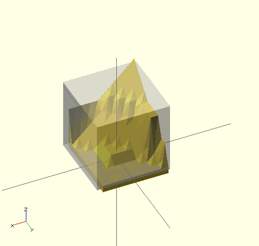
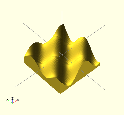
Example 2
 // example010.dat generated using octave:
 // d = (sin(1:0.2:10)' * cos(1:0.2:10)) * 10;
 // save("example010.dat", "d");
 intersection() {
   surface(file = "example010.dat", center = true, convexity = 5);
   rotate(45, [0, 0, 1]) surface(file = "example010.dat", center = true, convexity = 5);
 }
Example 3:
[Note: Requires version 2015.03]
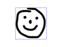
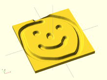
// Example 3a
scale([1, 1, 0.1])
  surface(file = "smiley.png", center = true);
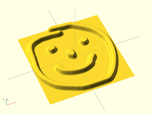
// Example 3b
scale([1, 1, 0.1])
  surface(file = "smiley.png", center = true, invert = true);