All 2D primitives can be transformed with 3D transformations. Usually used as part of a 3D extrusion. Although infinitely thin, they are rendered with a 1 thickness.
square
Creates a square or rectangle in the first quadrant. When center is true the square is centered on the origin. Argument names are optional if given in the order shown here.
square(size = [x, y], center = true/false);
square(size =  x    , center = true/false);
- parameters:
- size
- single value, square with both sides this length
- 2 value array [x,y], rectangle with dimensions x and y
- center
- false (default), 1st (positive) quadrant, one corner at (0,0)
- true, square is centered at (0,0)
- size
default values: square(); yields: square(size = [1, 1], center = false);
- examples:
equivalent scripts for this example
 square(size = 10);
 square(10);
 square([10,10]);
 .
 square(10,false);
 square([10,10],false);
 square([10,10],center=false);
 square(size = [10, 10], center = false);
 square(center = false,size = [10, 10] );
equivalent scripts for this example
 square([20,10],true);
 a=[20,10];square(a,true);
circle
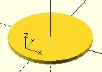
Creates a circle at the origin. All parameters, except r, must be named.
circle(r=radius | d=diameter);
- Parameters
- r : circle radius. r name is the only one optional with circle.
- circle resolution is based on size, using $fa or $fs.
- r : circle radius. r name is the only one optional with circle.
- For a small, high resolution circle you can make a large circle, then scale it down, or you could set $fn or other special variables. Note: These examples exceed the resolution of a 3d printer as well as of the display screen.
scale([1/100, 1/100, 1/100]) circle(200); // create a high resolution circle with a radius of 2.
circle(2, $fn=50);                        // Another way.
- d : circle diameter (only available in versions later than 2014.03).
- $fa : minimum angle (in degrees) of each fragment.
- $fs : minimum circumferential length of each fragment.
- $fn : fixed number of fragments in 360 degrees. Values of 3 or more override $fa and $fs
- $fa, $fs and $fn must be named. click here for more details,.
defaults: circle(); yields: circle($fn = 0, $fa = 12, $fs = 2, r = 1);
equivalent scripts for this example
 circle(10);
 circle(r=10);
 circle(d=20);
 circle(d=2+9*2);
ellipse
An ellipse can be created from a circle by using either scale() or resize() to make the x and y dimensions unequal. See OpenSCAD User Manual/Transformations
equivalent scripts for this example
 resize([30,10])circle(d=20);
 scale([1.5,.5])circle(d=20);
regular polygon
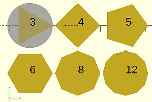
A regular polygon of 3 or more sides can be created by using circle() with $fn set to the number of sides. The following two pieces of code are equivalent.
circle(r=1, $fn=4);
 module regular_polygon(order = 4, r=1){
     angles=[ for (i = [0:order-1]) i*(360/order) ];
     coords=[ for (th=angles) [r*cos(th), r*sin(th)] ];
     polygon(coords);
 }
 regular_polygon();
These result in the following shapes, where the polygon is inscribed within the circle with all sides (and angles) equal. One corner points to the positive x direction. For irregular shapes see the polygon primitive below.
script for these examples
 translate([-42,  0]){circle(20,$fn=3);%circle(20,$fn=90);}
 translate([  0,  0]) circle(20,$fn=4);
 translate([ 42,  0]) circle(20,$fn=5);
 translate([-42,-42]) circle(20,$fn=6);
 translate([  0,-42]) circle(20,$fn=8);
 translate([ 42,-42]) circle(20,$fn=12);
 color("black"){
     translate([-42,  0,1])text("3",7,,center);
     translate([  0,  0,1])text("4",7,,center);
     translate([ 42,  0,1])text("5",7,,center);
     translate([-42,-42,1])text("6",7,,center);
     translate([  0,-42,1])text("8",7,,center);
     translate([ 42,-42,1])text("12",7,,center);
 }
polygon
Creates a multiple sided shape from a list of x,y coordinates. A polygon is the most powerful 2D object. It can create anything that circle and squares can, as well as much more. This includes irregular shapes with both concave and convex edges. In addition it can place holes within that shape.
polygon(points = [ [x, y], ... ], paths = [ [p1, p2, p3..], ...], convexity = N);
- Parameters
- points
- The list of x,y points of the polygon. : A vector of 2 element vectors.
- Note: points are indexed from 0 to n-1.
- paths
- default
- If no path is specified, all points are used in the order listed.
- single vector
- The order to traverse the points. Uses indices from 0 to n-1. May be in a different order and use all or part, of the points listed.
- multiple vectors
- Creates primary and secondary shapes. Secondary shapes are subtracted from the primary shape (like difference). Secondary shapes may be wholly or partially within the primary shape.
- default
- A closed shape is created by returning from the last point specified to the first.
- convexity
-
- Integer number of "inward" curves, ie. expected path crossings of an arbitrary line through the polygon. See below.
defaults: polygon(); yields: polygon(points = undef, paths = undef, convexity = 1);
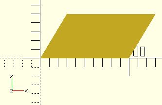
- Example no holes
equivalent scripts for this example
 polygon(points=[[0,0],[100,0],[130,50],[30,50]]);
 polygon([[0,0],[100,0],[130,50],[30,50]], paths=[[0,1,2,3]]);
 polygon([[0,0],[100,0],[130,50],[30,50]],[[3,2,1,0]]);
 polygon([[0,0],[100,0],[130,50],[30,50]],[[1,0,3,2]]);

 a=[[0,0],[100,0],[130,50],[30,50]];
 b=[[3,0,1,2]];
 polygon(a);
 polygon(a,b);
 polygon(a,[[2,3,0,1,2]]);
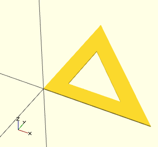
- Example one hole
equivalent scripts for this example
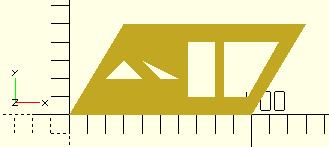
 polygon(points=[[0,0],[100,0],[0,100],[10,10],[80,10],[10,80]], paths=[[0,1,2],[3,4,5]],convexity=10);

 triangle_points =[[0,0],[100,0],[0,100],[10,10],[80,10],[10,80]];
 triangle_paths =[[0,1,2],[3,4,5]];
 polygon(triangle_points,triangle_paths,10);
The 1st path vector, [0,1,2], selects the points, [0,0],[100,0],[0,100], for the primary shape.
The 2nd path vector, [3,4,5], selects the points, [10,10],[80,10],[10,80], for the secondary shape.
The secondary shape is subtracted from the primary ( think difference() ).
Since the secondary is wholly within the primary, it leaves a shape with a hole.
- Example multi hole
[Note: Requires version 2015.03] (for use of concat())
      //example polygon with multiple holes
a0 = [[0,0],[100,0],[130,50],[30,50]];     // main
b0 = [1,0,3,2];
a1 = [[20,20],[40,20],[30,30]];            // hole 1
b1 = [4,5,6];
a2 = [[50,20],[60,20],[40,30]];            // hole 2
b2 = [7,8,9];
a3 = [[65,10],[80,10],[80,40],[65,40]];    // hole 3
b3 = [10,11,12,13];
a4 = [[98,10],[115,40],[85,40],[85,10]];   // hole 4
b4 = [14,15,16,17];
a  = concat (a0,a1,a2,a3,a4);
b  = [b0,b1,b2,b3,b4];
polygon(a,b);
      //alternate
polygon(a,[b0,b1,b2,b3,b4]);
- convexity
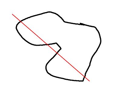
The convexity parameter specifies the maximum number of front sides (back sides) a ray intersecting the object might penetrate. This parameter is needed only for correct display of the object in OpenCSG preview mode and has no effect on the polyhedron rendering.
This image shows a 2D shape with a convexity of 4, as the ray indicated in red crosses the 2D shape a maximum of 4 times. The convexity of a 3D shape would be determined in a similar way. Setting it to 10 should work fine for most cases.
import_dxf
[Deprecated: import_dxf() will be removed in future releases. Use import() instead.]
Read a DXF file and create a 2D shape.
Example
linear_extrude(height = 5, center = true, convexity = 10)
        import_dxf(file = "example009.dxf", layer = "plate");


